Custom Pedal • Circuit Development
Dual-Stage Power Boost.
Two boosts. One small tin.
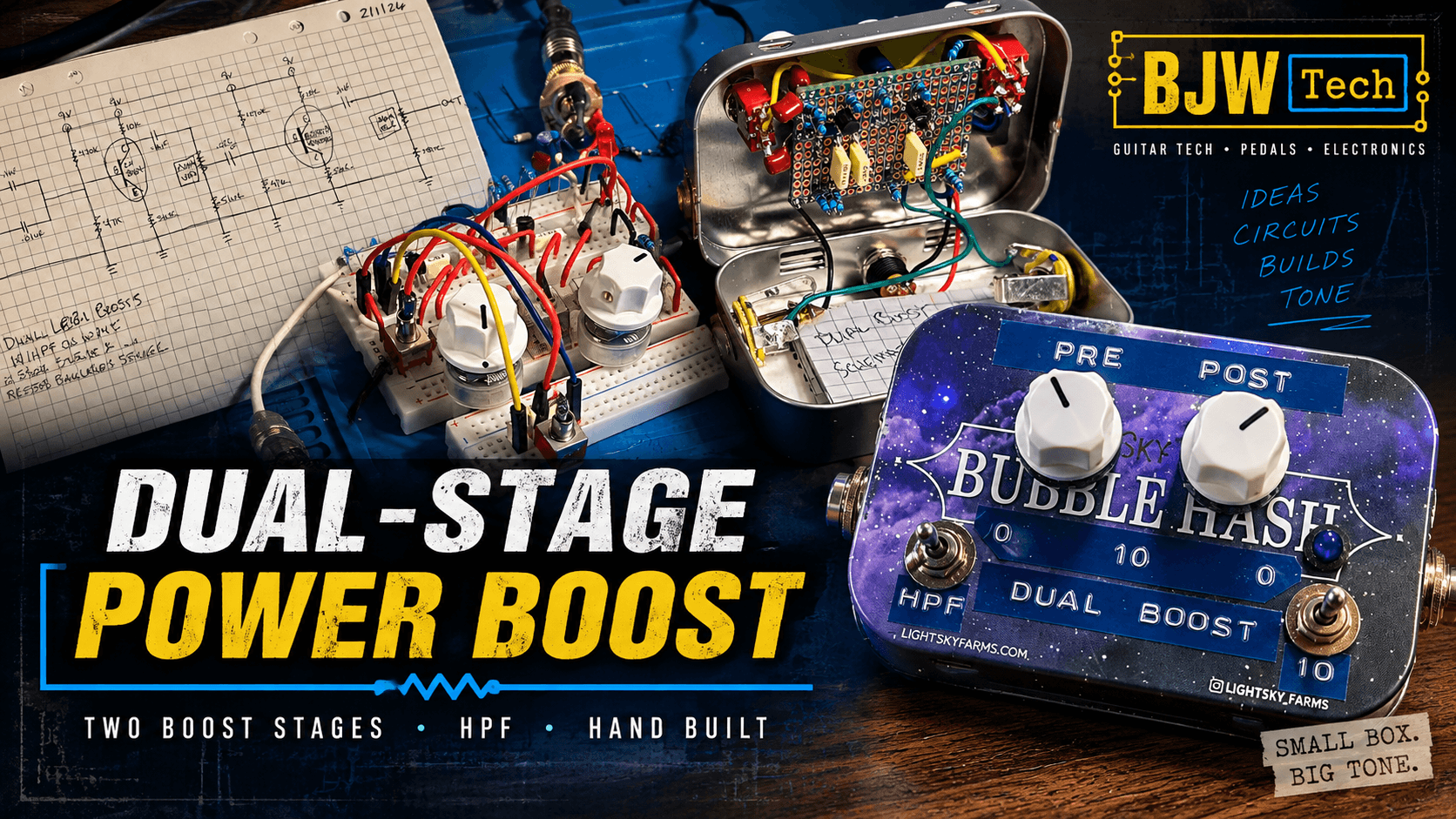
A compact two-stage transistor power booster built around a classic linear power booster design, with PRE and POST level controls, a switchable input low-cut, and enough range to move from added level into some grit when pushed.
01 • The Idea
Put the boost stack in one pedal.
I’ve always liked stacking boosts on a pedalboard, as well as running a boost into an overdrive. A simple power boost can add level, but when one gain stage starts pushing another it can also add some useful grit and change the way the next stage responds.
This build grew out of that idea: take two classic transistor power-boost stages, cascade them inside one pedal, and keep control over what happens between the stages and at the final output.
02 • Circuit Development
From sketch to breadboard.
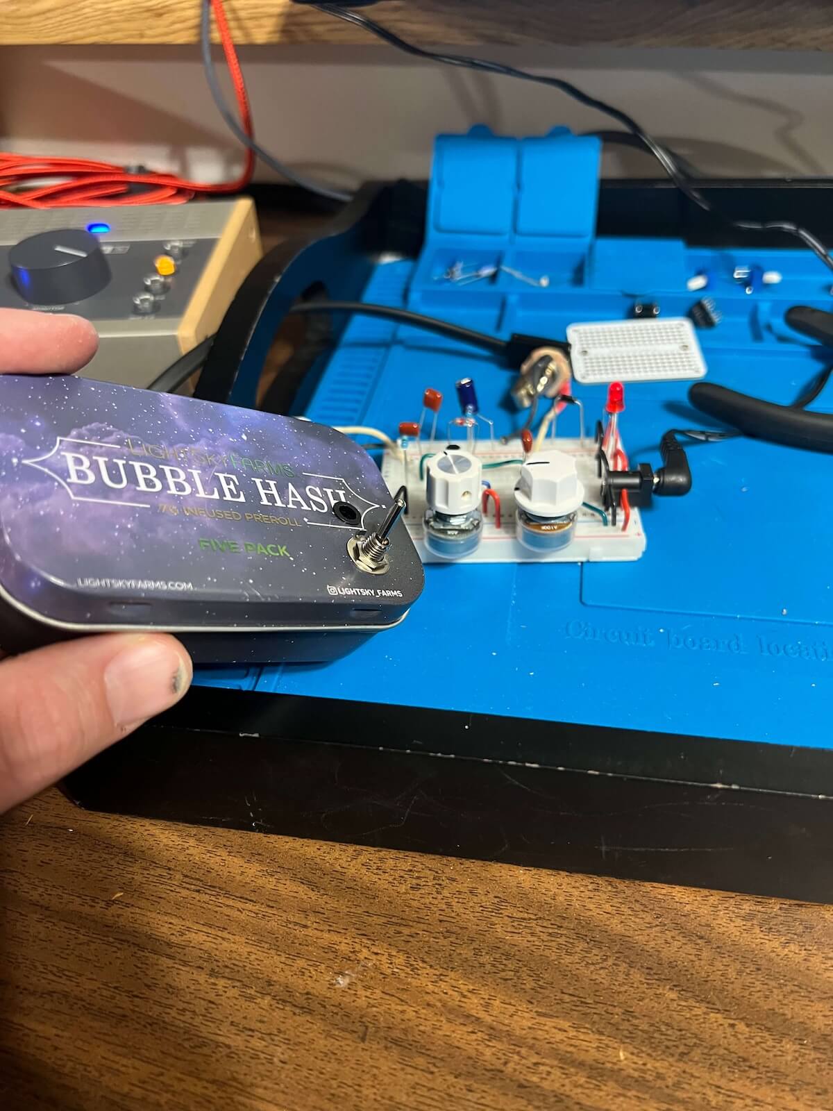
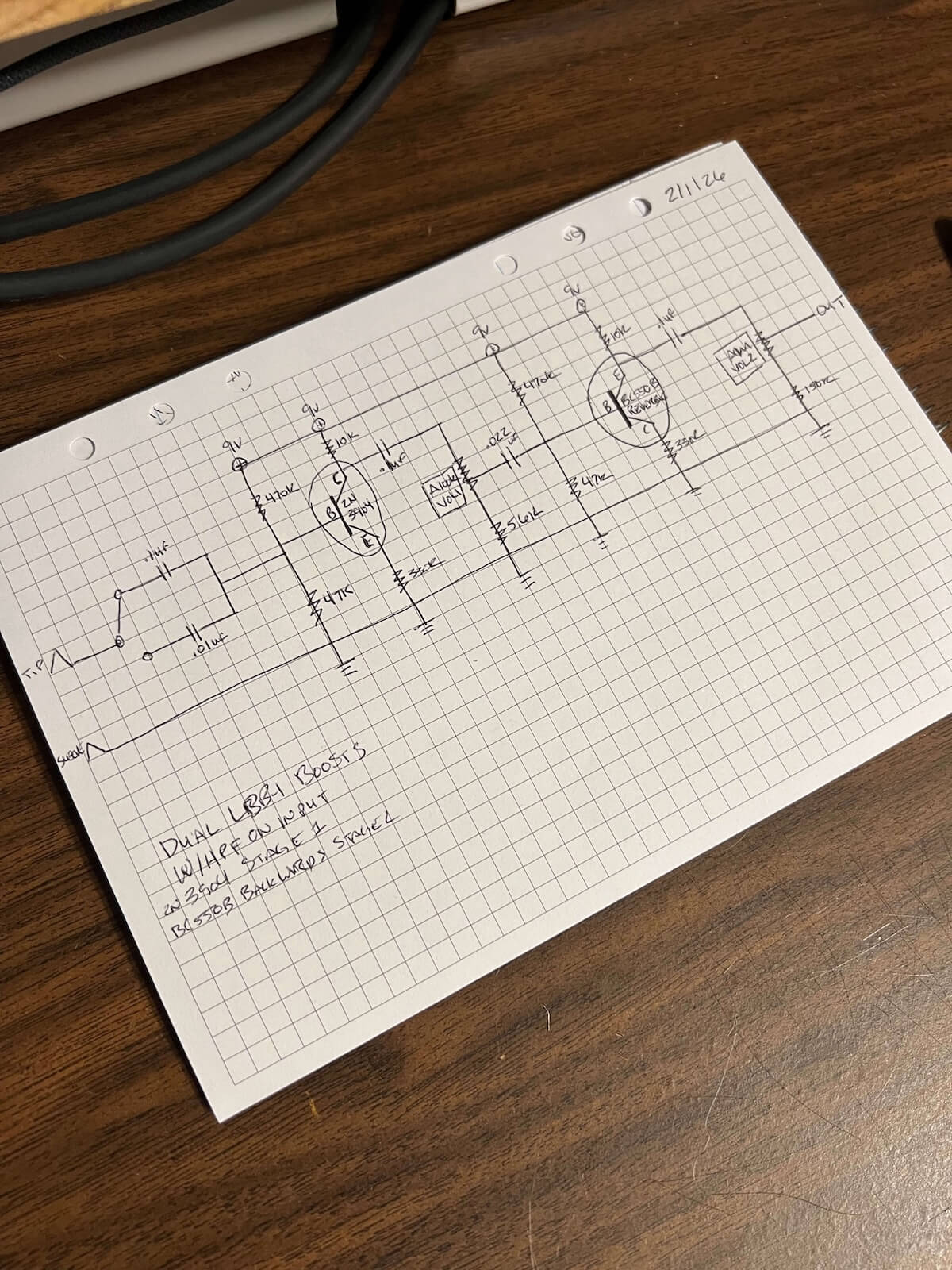
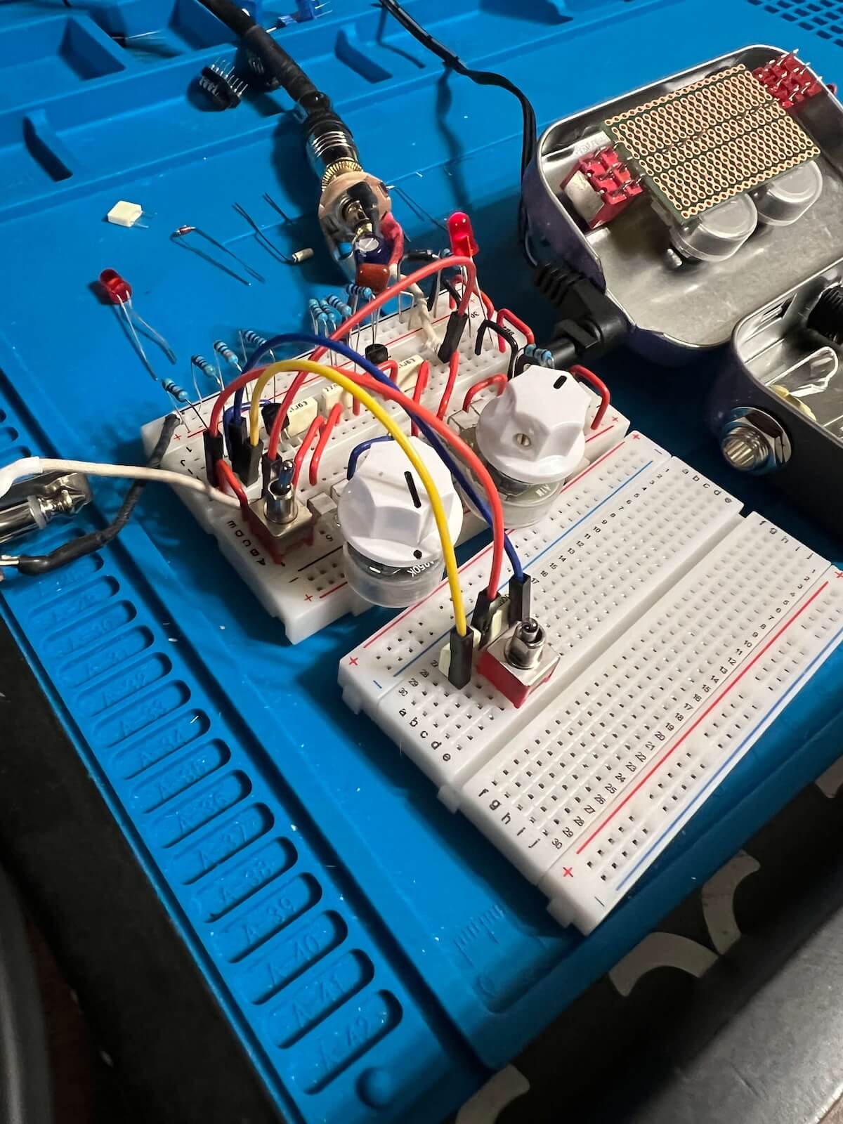
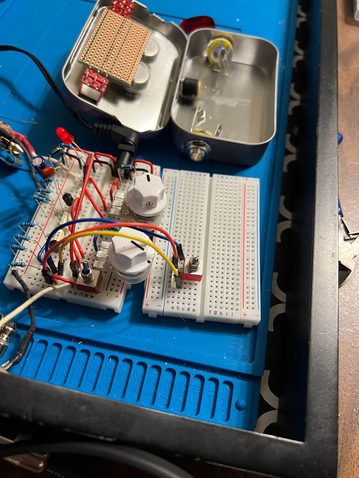
The circuit started with a hand-drawn schematic and was developed on the breadboard before anything was committed to perfboard. That made it possible to work through the two-stage boost, the level controls and the low-cut while the circuit was still easy to change.
03 • PRE + POST
Two stages, two different jobs.
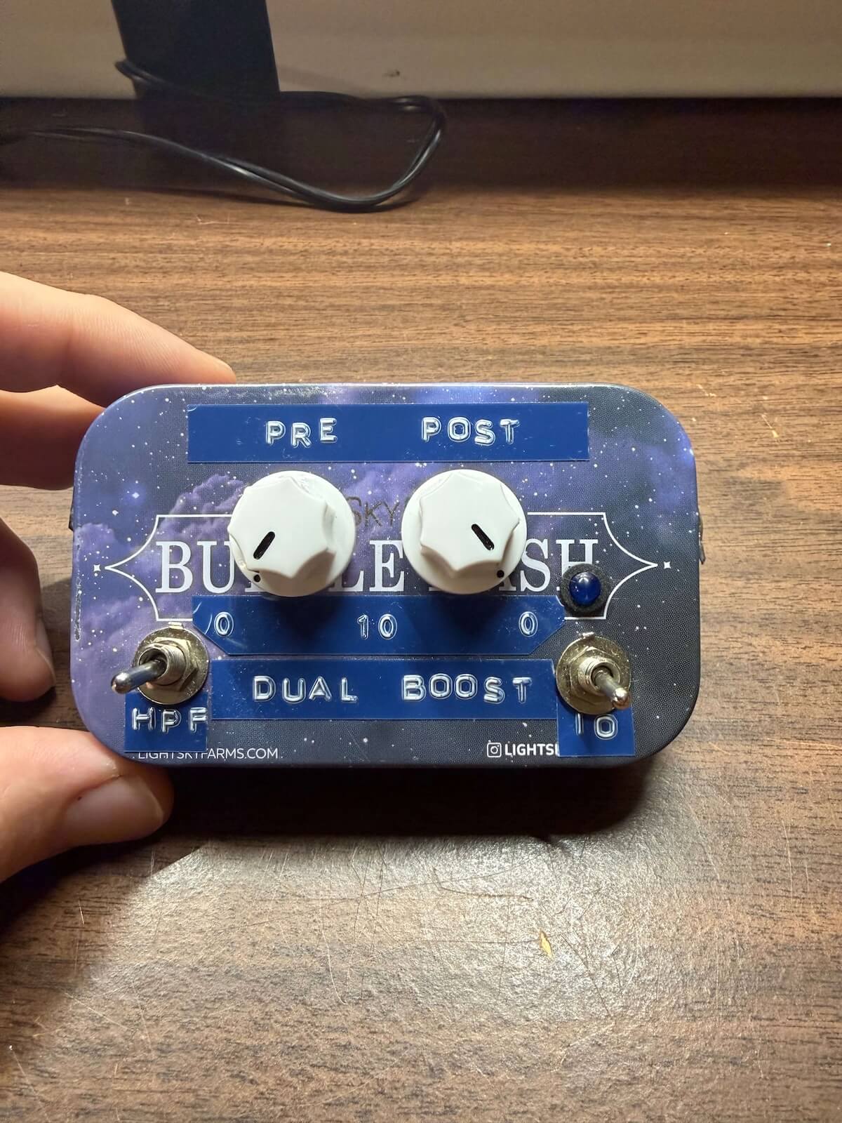
PRE controls the output of the first boost stage feeding the second. Turning it up doesn’t just make the pedal louder — it determines how hard the second stage is being driven, letting the stacked circuit move from cleaner boost toward more grit.
POST controls the output after the second boost stage, providing the final level control for the pedal.
I’ve built larger versions of this idea with each boost independently footswitchable. The tin used for this build had much tighter size constraints, so this version keeps the two stages permanently cascaded and concentrates the controls on PRE, POST and the switchable filter.
04 • Switchable Low-Cut
Trim the rumble. Keep the thump.
This pedal was designed for a spot in my signal chain after an octave effect that can generate a −1 octave sub tone. That extra-low content can get overly rumbly once it hits a boost — and even more so when one boost stage is driving another.
The solution was a switchable high-pass filter at the very beginning of the circuit. It trims some of that excessive sub-bass before either boost stage amplifies it, without stripping away all of the low-end weight and thump. When that filtering isn’t needed, it can be switched out.
05 • Breadboard to Perfboard
Making the prototype permanent.
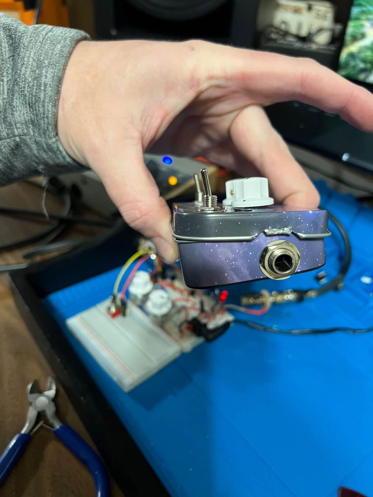
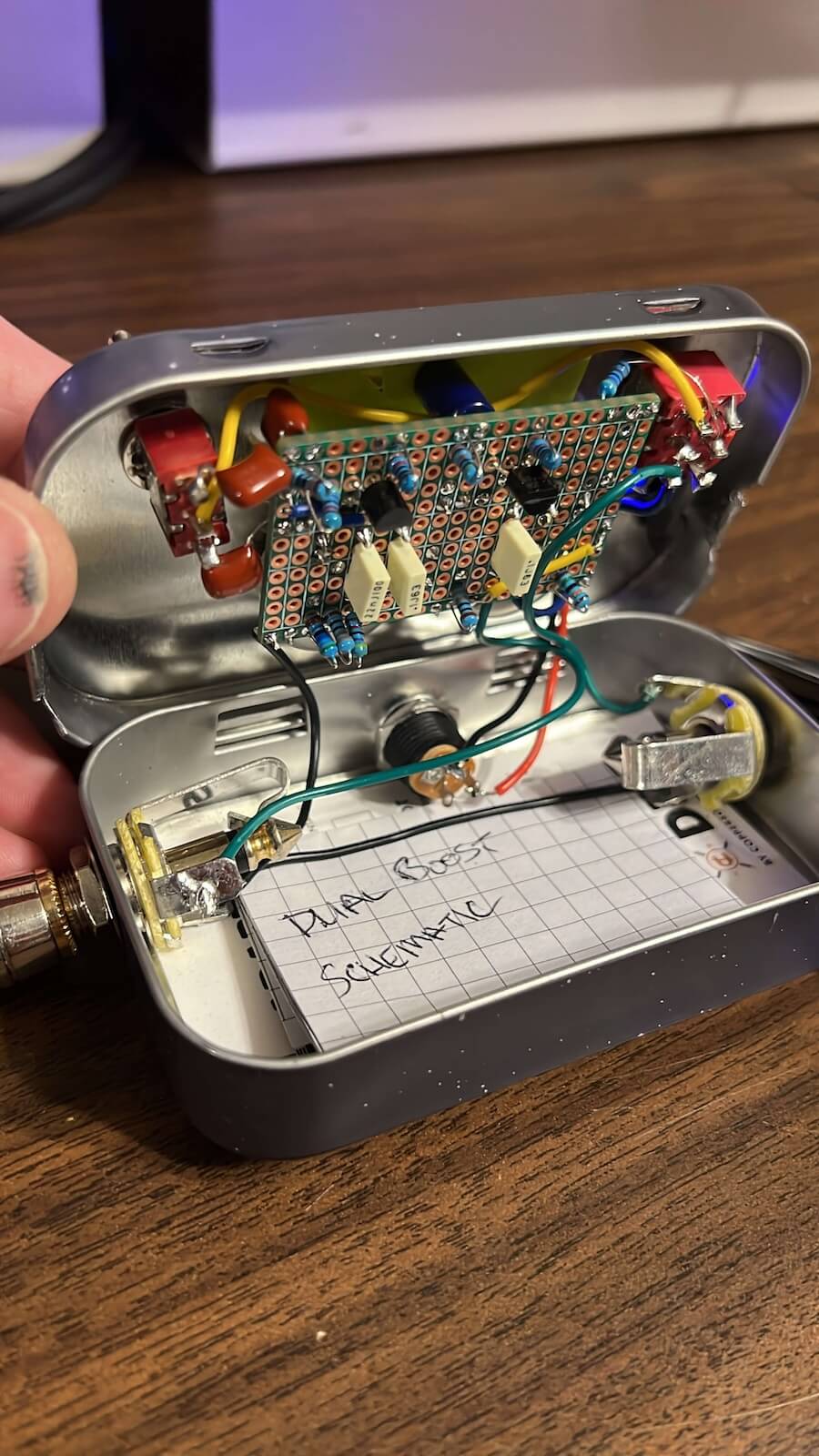
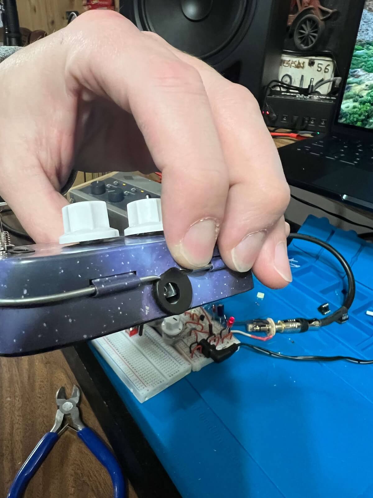
Once the circuit was behaving the way I wanted, the breadboard design was transferred to perfboard and laid out around the space available inside the enclosure. The electrical design was only half the job — the board, pots, switches, LED, jacks, power connection and wiring all had to coexist in a very small footprint.
06 • The Enclosure
The tin set the rules.
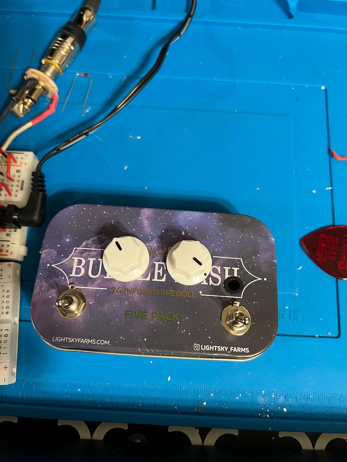
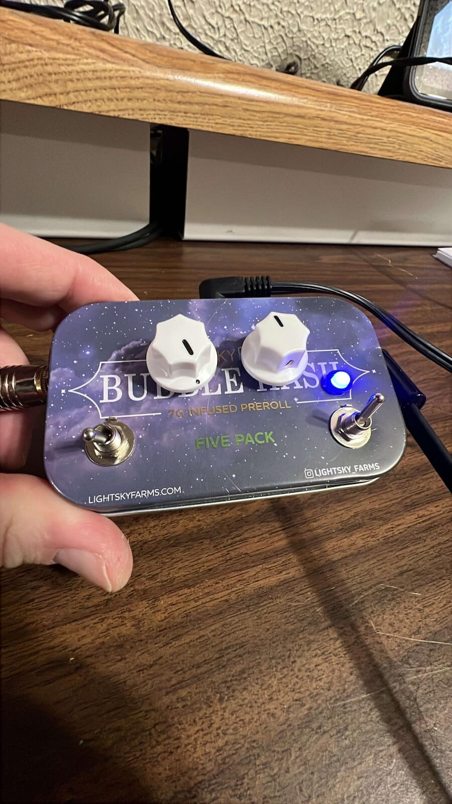
The recycled tin made a fun enclosure, but it also imposed real mechanical constraints. There wasn’t room for the independent footswitching used on my larger dual-boost versions, so the layout was simplified around the controls that mattered most for this build.
The finished top panel keeps things straightforward: PRE and POST controls, the low-cut switch, power/status indication and simple embossed labels. The same Dymo-style labeling has since become part of the visual language I use on other custom builds.
07 • The Result
A boost built for how I actually use boosts.
The finished pedal combines two cascaded classic power-boost stages with control over how hard the second stage is driven, plus an input filter designed around a real problem in the signal chain. It can add level, push into some grit, and keep octave-down content from turning into uncontrolled low-end rumble.
Bench Video
Have an Idea?
Custom pedals don’t have to start with a kit.
If you’ve got an idea for a boost, filter, utility pedal or another custom electronics project, get in touch and we’ll talk through what’s possible.
Discuss a Project